Static Simulation - Beam Simulation
Static Simulation is a method that uses finite element method with independent of time to avoid mistakes on the design process. We can determine design parameters in beams by using finite element method to predict deformations beforehand.
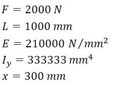
Values that will be used in beam simulation will be taken from "1-Simple Beam - Load Concentrated at the Center" in Calculations-Beam Calculations. Simulation will be done in Solidworks Static Simulation.

Center is at the A point
Firstly beam is designed in Solidworks. Let's assume beam cross-section is square. We'll calculate edge length of the square from moment of inertia in our example.


Beam is designed in Solidworks according to example. Make sure center point is at the A point.

Let's split the bottum surface into two section. Assign a point on the center of the top surface and select a material that has the same elasticity module as the example.

Activate Solidworks Simulation and click static simulation. First we need to define support in A and B points. Since Point A is a fixed support, we need to select fixed geometry and apply it to A point.

Since Point B is a sliding support and movement is allowed only in X direction we can't fix the geometry in 3 directions. Instead of this right click fixtures and select "advanced fixtures". Select the edge that is the Point B, "Front Plane" as reference plane and activate the directions that the movement is not allowed. Only the direction that movement is allowed is not activated.

Select "Force" from "External Loads" and apply it to the point that is on the middle of the top surface. Make sure it's pointed downwards and 2000N.

Create the mesh and run the simulation.

Double click deformation from the results section and we'll see the results as shown below. Maximum deformation is 0,601 mm. In the example that is in section "1-Simple Beam-Load Concentrated at the Center" we found the result as 0,6 mm

To find the deformation at the "x" length, right click deformation and click "Probe". Select "On Selected Entities" from Options. Previously we split the bottom surface. Select the edge between these surfaces and click update. On the "X (mm)" column we find the 300 mm and the value is 0,474 mm. In the example of "1-Simple Beam-Load Concentrated at the Center" section we found the value for x=300 mm as 0,47 mm.
